Tube Settler Media Retrofit: What to Check Before Selection
Check hydraulics, loading, support, sludge removal and cleaning before selecting tube settler media for a clarifier retrofit.
By Puyu Environmental ·
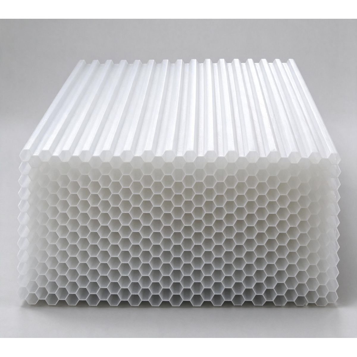
Tube settler media is one part of the clarifier
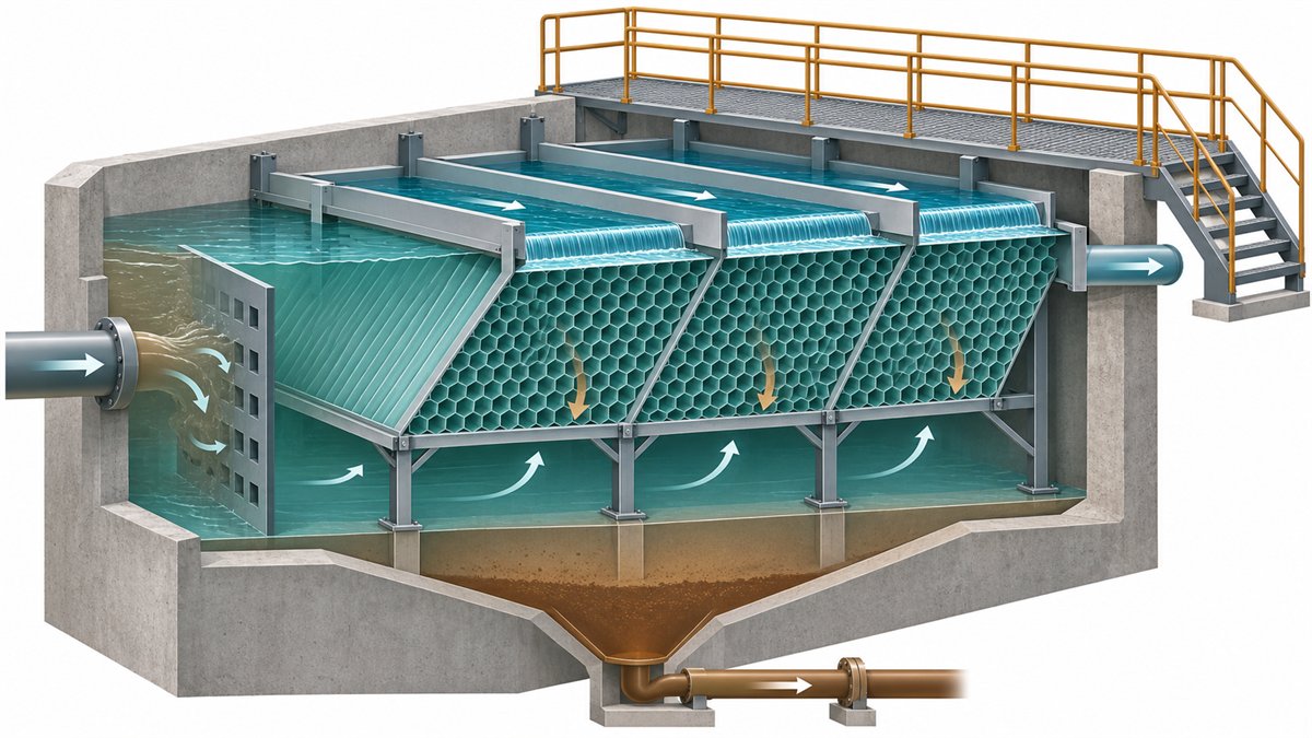
Tube settler media shortens the distance that a particle must settle before reaching a surface. The inclined passages provide many shallow settling zones within a clarifier, while collected solids are intended to slide toward the sludge zone under suitable operating conditions. This can improve clarification or help a basin handle a revised duty, but the media is only one part of the separation system.
A retrofit should therefore begin with the clarifier and the water being treated, not with a request for a price per cubic metre of media. Inlet energy, flow distribution, floc characteristics, available module area, effluent collection, sludge removal and cleaning access all affect whether the installed system can use the added settling area.
Define the treatment duty before selecting a module
State whether the project treats drinking water, municipal wastewater, industrial wastewater or a tertiary coagulation stream. Tube settlers have been used in more than one of these services, but the pretreatment, solids behavior and acceptance criteria differ. A drinking-water rule, an industrial wastewater example and a secondary-clarifier retrofit should not be treated as interchangeable design precedents.
Document the operating cases that matter: average flow, peak flow and duration, recycle streams, startup or wash-water returns, expected suspended solids, temperature range, chemical conditioning and the required effluent quality. Where coagulation and flocculation are part of the process, record the chemical and mixing basis because the settler receives the floc that those upstream steps create.
If the water or solids behavior is uncertain, plan for jar testing, settling tests, pilot work or a controlled in-plant trial as directed by the project engineer and applicable authority. Massachusetts' 2026 public-water treatment guidance, for example, calls for tube or plate settler effectiveness to be demonstrated by piloting and allows higher application rates only when supported by demonstration. That is a useful warning against copying a loading rate from another project; it is not a universal design rule for every jurisdiction or wastewater service.
Check the hydraulic path, not only the media area
Uneven flow can waste a large part of the installed module area. Map the path from the basin inlet to the space below the modules, upward through the passages and into the effluent launders or weirs. Look for a short path from inlet to outlet, submerged jets, dead zones, uneven water level, obstructions and a concentration of flow beneath only part of the media.
The US EPA design references describe flow distribution and sludge removal as practical constraints in shallow settling systems. EPA guidance for existing drinking-water basins also shows collection troughs across the covered area to promote uniform withdrawal. A retrofit review should therefore include the inlet baffles, module coverage, clear space around the modules, launder arrangement and weir leveling rather than treating the modules as an isolated insert.
Ask the designer to show the hydraulic basis for average and peak cases. A proposed increase in flow is not justified merely because the projected settling area has increased. The basin must still distribute that flow without carrying unsettled solids directly to the outlet.
Make the loading-rate basis explicit
Quotations may refer to basin surface overflow rate, tube cross-sectional area, projected horizontal area, effective settling area or a supplier-specific calculation. These bases are not automatically equivalent. Each quoted value should identify its denominator, units, design flow and any reduction for blocked, edge or inactive areas.
Use one documented basis when comparing offers. Ask for a layout showing the installed module footprint and the area actually included in the calculation. Record whether the calculation uses average flow, maximum day, peak hour or another defined condition. If a supplier cites a regulatory or handbook limit, confirm that it applies to the project type, temperature, pretreatment and local authority.
The approval calculation belongs to the responsible process engineer. A media supplier can provide module geometry and product limits, but should not silently select the project loading rate without the water-quality and hydraulic basis.
Verify the retrofit envelope and structural support
Survey the existing basin before requesting final dimensions. Record internal length and width, operating water levels, inlet and outlet elevations, sludge-zone depth, scraper or suction equipment, access openings, walls, columns, pipes, launders and any equipment that crosses the proposed module zone.
The support system must carry the modules and the defined installation and maintenance loads without blocking the required hydraulic and sludge paths. Request a support drawing that identifies bearing points, module orientation, restraint, edge closure and removal sequence. Confirm which party designs and supplies the support structure; do not assume it is included with loose media blocks.
Also check the vertical clearances above and below the modules. Space below the media is needed for reasonably uniform approach flow and for solids to reach the sludge-collection zone. Space above it is needed for effluent collection, inspection and cleaning. The required dimensions are project-specific and should be shown on the approved basin drawing.
Keep sludge and scum management in the design
Tube settlers separate solids; they do not remove those solids from the plant. Confirm how settled material moves from the module surfaces into the hopper or basin floor and how the existing scraper, suction or blowdown system removes it. Review sludge-withdrawal capacity and frequency under the revised solids load.
Floating material also needs a defined route. A module layout that traps scum, biological growth or debris can obstruct passages and complicate cleaning. Identify any open scum zone, baffle, skimmer or operating procedure needed for the actual service.
For a secondary biological clarifier, do not assume experience from a coagulation-sedimentation basin transfers directly. Activated-sludge settling, blanket behavior, return-sludge operation and gas formation introduce different risks. The project engineer should evaluate whether tube settlers are appropriate for that solids system before the product is ordered.
Design cleaning, drainage and safe access before startup
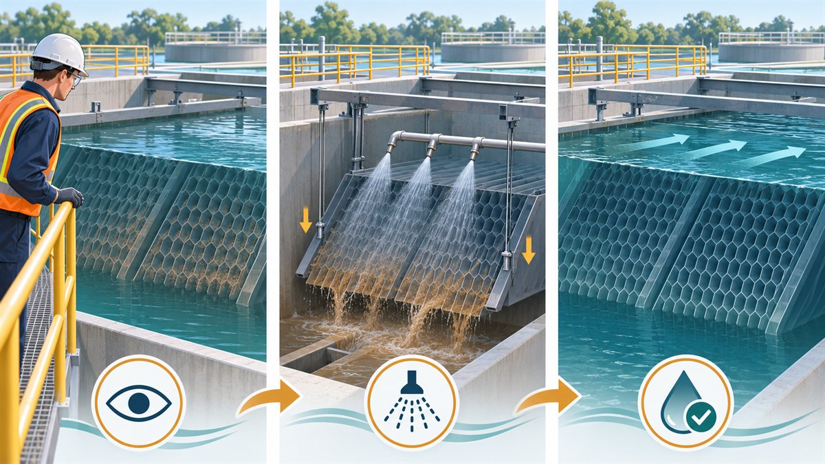
Fouling is an operating condition, not an afterthought. The EPA suspended-solids manual records sludge accumulation on upper tube surfaces in wastewater applications and describes periodic air cleaning. Massachusetts' 2026 public-water treatment guidance requires water and/or air flushing provisions for routine removal of floc buildup and drainage sized for a rapid flush.
The correct cleaning method depends on the media, contaminants and plant arrangement. Ask for the supplier's written cleaning limits and make the plant procedure specific: isolation requirements, whether the basin must be lowered or drained, water or air source, allowable pressure, waste destination, inspection points and the method for returning the unit to service.
Provide safe access without treating the media as a walkway. Define platforms, removable covers, lifting points and confined-space controls according to the site design and local safety requirements. A module that cannot be inspected or removed without damaging adjacent equipment creates a long-term maintenance risk.
Compare the exact product offered
Request the exact model and drawing revision. The submittal should identify passage shape and nominal opening, module dimensions and orientation, material declaration, joining or block-assembly method, stated temperature limits, support requirements, module weight and packing configuration. Treat these as supplier-specific product data that needs confirmation for the offered item.
Do not infer Puyu product dimensions, material grade, loading capacity or service life from another manufacturer's literature. Third-party manuals can explain separation principles and design interfaces; they cannot certify the construction or performance of the product being quoted.
Where the existing basin, water or operating environment may affect material compatibility, send the relevant chemical, temperature and exposure information and obtain a written recommendation. Record any exclusions, expected field cutting and site assembly responsibilities.
Information to include in a tube settler RFQ
A technically useful request should make missing information visible instead of replacing it with assumptions.
- Process and service: drinking water, municipal wastewater, industrial wastewater or tertiary treatment; new basin or retrofit.
- Design flows: minimum, average, maximum and peak values, durations and recycle or return streams.
- Influent and required effluent data: suspended solids, turbidity where relevant, temperature and the sampling basis.
- Pretreatment: screening, coagulation, flocculation, pH adjustment and any upstream process that controls particle behavior.
- Basin survey: internal dimensions, water levels, inlet and outlet details, launders, sludge equipment, obstructions and access.
- Hydraulic basis: proposed module coverage, distribution method, loading-rate definition and peak-flow check.
- Solids management: sludge quantity basis, hopper or floor arrangement, withdrawal method, scum handling and waste destination.
- Cleaning and access: flushing source, drainage, isolation, inspection, lifting and removal plan.
- Product submittal: exact model, drawing, material declaration, module dimensions, support loads and stated operating limits.
- Commercial scope: quantity, support structure, site assembly, spare blocks, packing, delivery destination and required documents.
A practical approval rule
Hold technical approval when a proposal gives only media dimensions, a surface-area figure and a unit price. Ask for the definition behind every area and loading value, a basin layout, the hydraulic and solids-removal basis, the support scope and a workable cleaning method.
Shortlist the option only when the responsible engineer can trace the complete flow and solids path through the modified basin and when the exact offered module fits the approved structure and maintenance plan. The purpose of a tube settler retrofit is dependable clarification under the stated operating cases, not the largest isolated area number in a quotation.
References
- US EPA — Process Design Manual for Suspended Solids Removal
- US EPA — Technologies for Upgrading Existing or Designing New Drinking Water Treatment Facilities
- US EPA — Long Term 1 Enhanced Surface Water Treatment Rule Turbidity Provisions Technical Guidance Manual
- Massachusetts Department of Environmental Protection — Guidelines for Public Water Systems, Chapter 5: Treatment
Related information
Discuss your application
Contact Puyu Environmental with your project requirements.